Clock Number 10
| This clock sets the pattern for future clocks because it truly is a Woodturners clock. It starts out as a lidded box which is one of the most common wood turning projects wood turners can make. While they are not difficult to make and can be made even by a novice woodturner, they are pleasant and satisfying projects. On this occasion as the pictures show I simply turned a lidded box, then turned some circles which I cut in thirds and mounted on the lidded box as a frame. Once that was done I created a movement to fit within the available space.
The movement I designed and built for this clock was developed from any number of failed experiments and it is true to say that there were times when it became so frustrating that I seriously considered abandoning the whole idea. The heart of the clock is a small switch (see electronics) that was developed by Bruce Breimon who lives in California and with whom I collaborated very closely. I have modified Bruce’s original switch to some extent but without the ingenious work Bruce did in the first place Clocks 9 and 10 would probably not have been built. You may also note that I have abandoned the traditional clock makers practice of crossing out the wheels by cutting spokes because, at the end of the day, I am interested in creating something unique. For this reason I have opted to lighten the weight of the wheels by drilling holes at regular intervals. I doubt that it is actually possible to do anything in clock making that has not been done before, but I have not seen any other clock maker using this sort of presentation. As a wood turner the object of my exercise is to create something that is unique and I think the different wheels do that. I am really quite excited about the developments that have happened in clock 10 because they will allow me to make simple but unique clocks that are relatively easy to build, achieve my original time keeping objective, an accuracy of 1 to 2 minutes a week and add to the world of wood turning. I have now almost competed a modification to clock 4 which has removed the pendulum and replaced it with a scaled up version of the lever system I have used in this clock. And let’s face it, anything that gets a septuagenarian excited has to be a good thing. |

The process in its very early stages. |
 Box turned and frame mounted. Box turned and frame mounted. |
 Designing the movement. I design by making there are no drawings. Designing the movement. I design by making there are no drawings. |
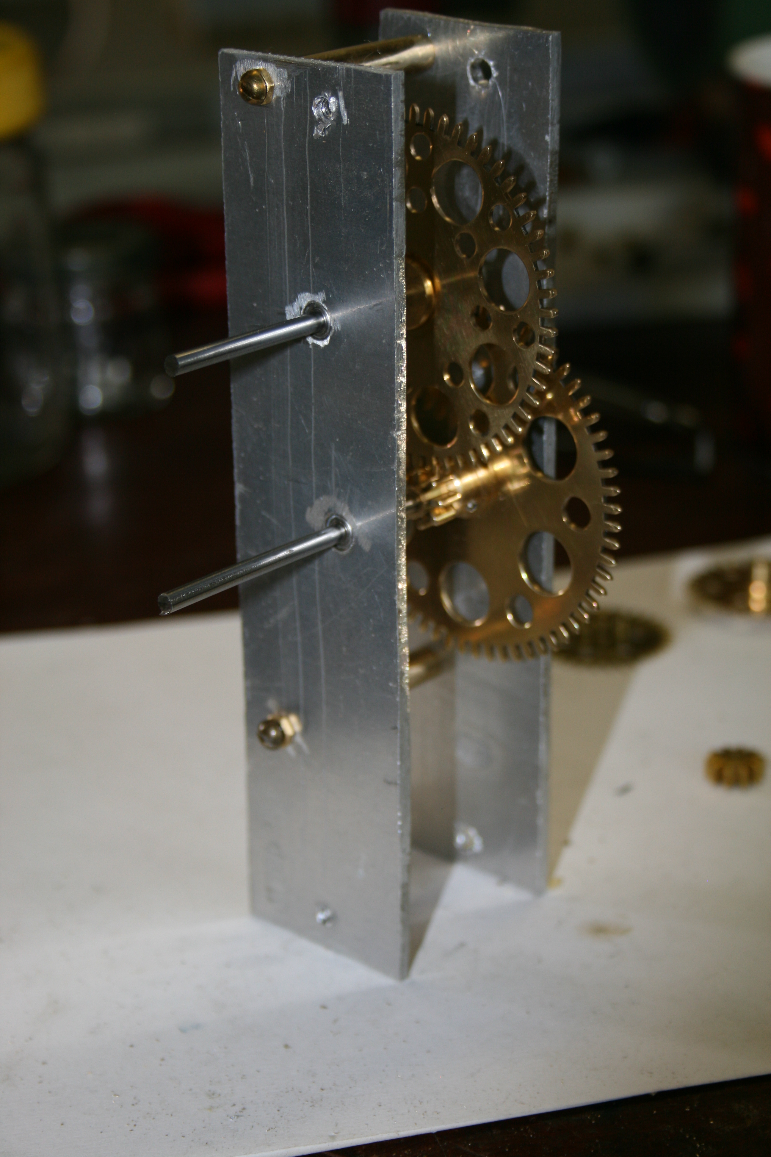
This is another view of the design process. |
Some experimentation. My original idea was to use a solenoid mounted on its side and this was one of the early experiments. |
The experiment continues. The solenoid is mounted in the frame and connected to the count wheel. |
I made a timber cover for the solenoid, added some more wheels to the movement and installed a better lever. By now it was becoming obvious that a solenoid on its side was going to be prone to sticking. So I had to change horses mid stream and come up with a better mouse trap. |
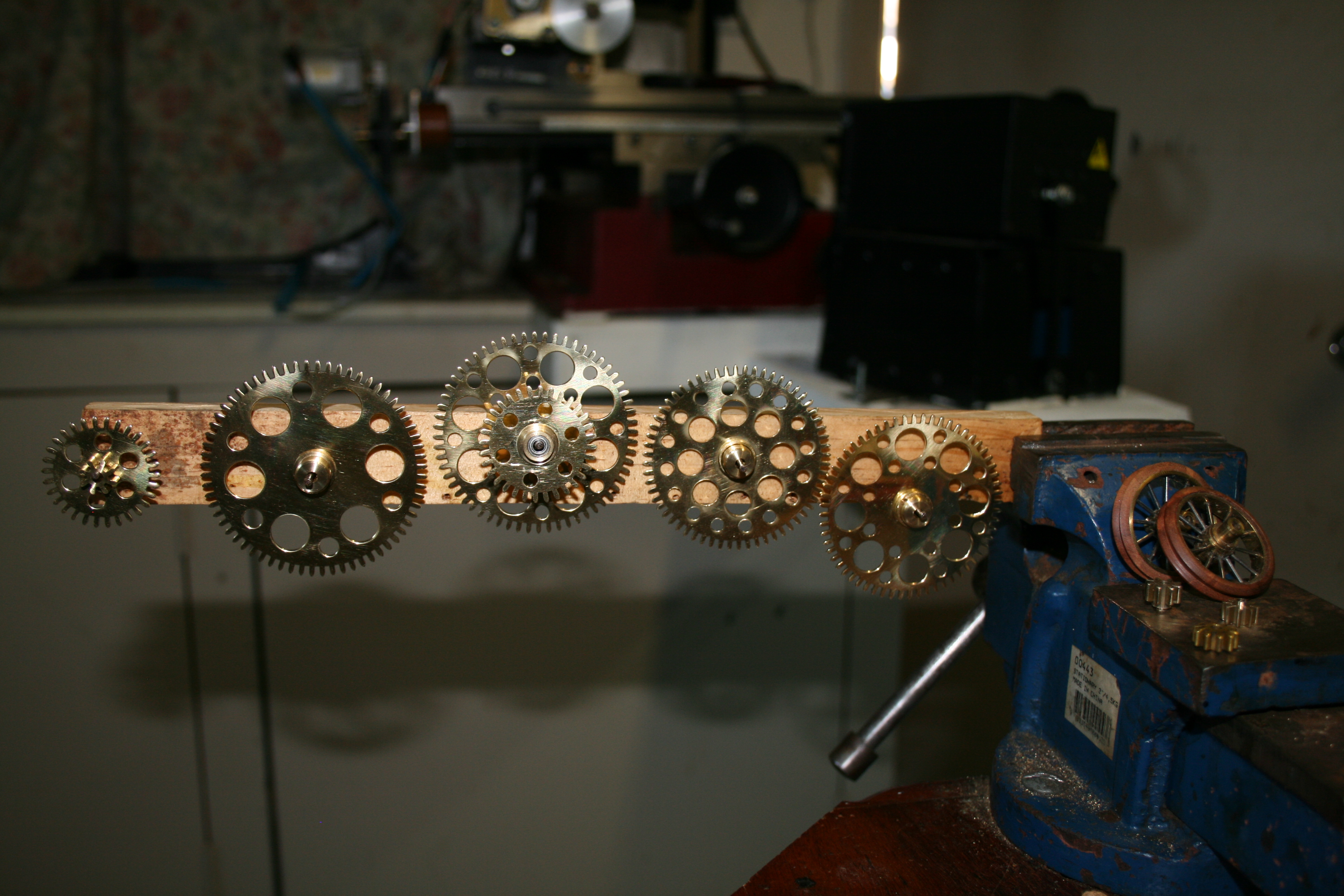
The wheels ready to install. They have been treated with thin coats of acrylic lacquer and heated with a heat gun between coats. |
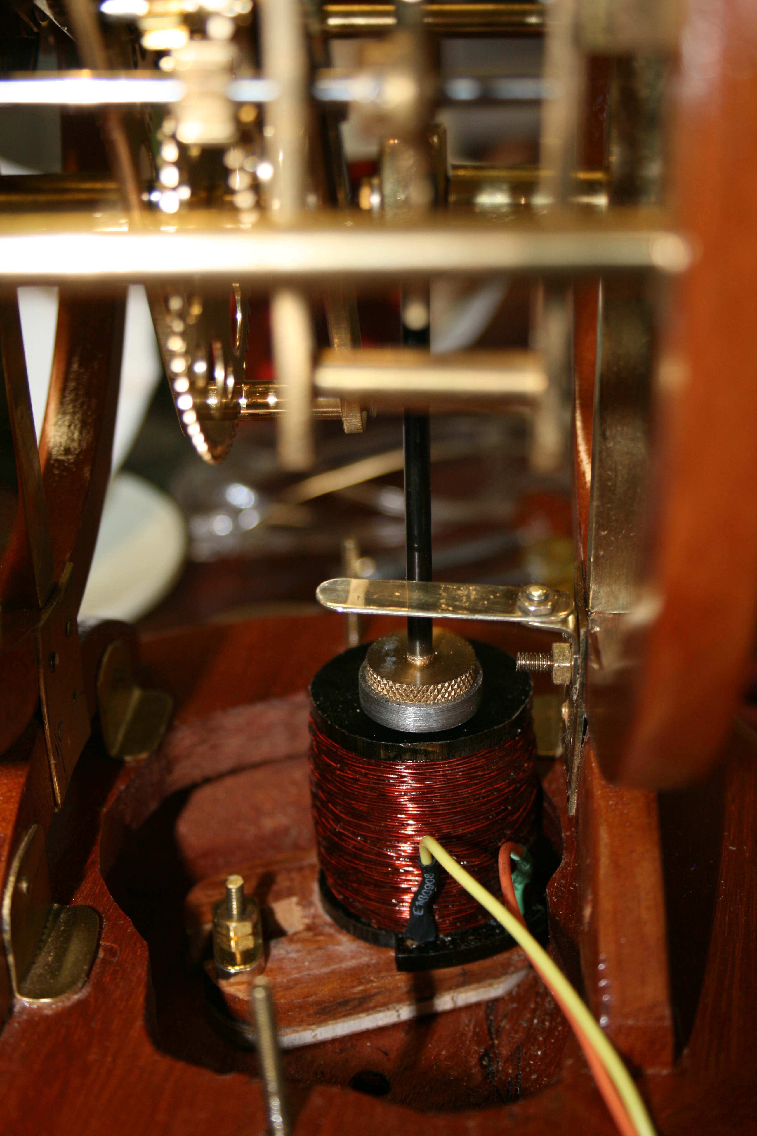
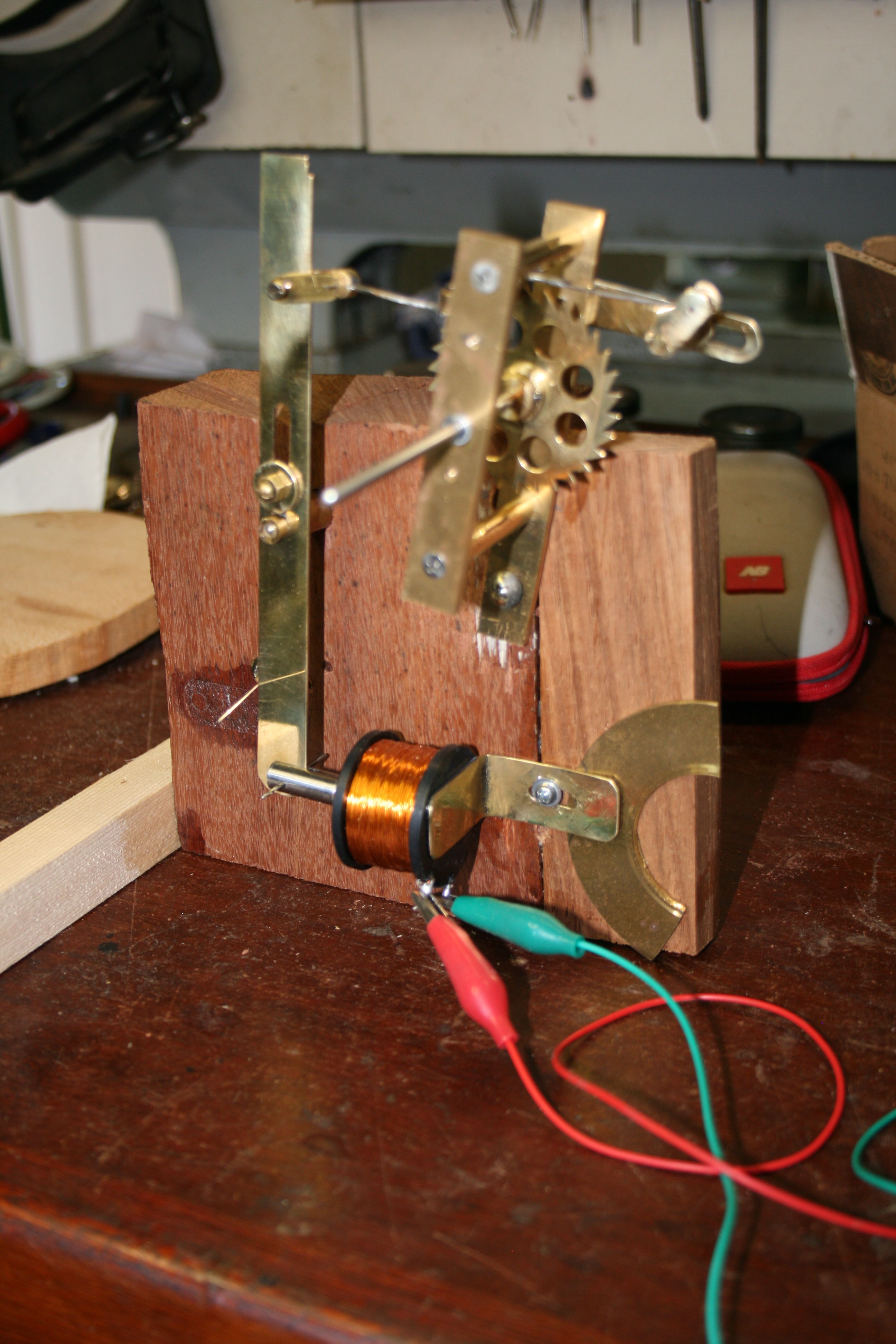
The different mouse trap. Rather than using a solenoid on its side I decided to use a solid coil and place the armature above it. The principal is the same as that used for my pendulum clocks where the armature is attracted by the magnetic force when the coil is switched on. However the question was how do I get the armature to return to its home position after the coil is turned off. I began experimenting with a counter weight. |
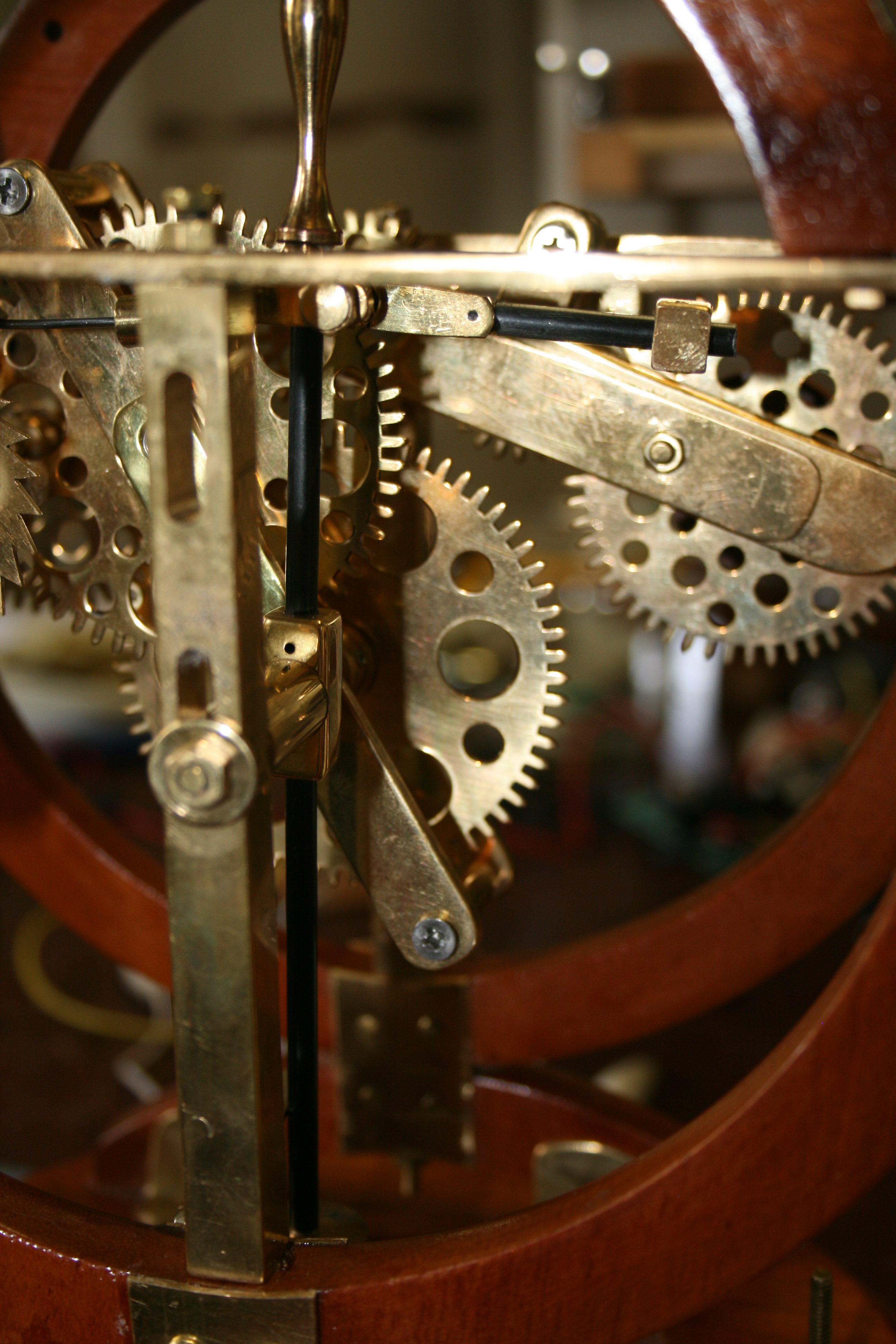
The counter weight. The black perpendicular black rod has a push rod on the left to push the count wheel when the coil is turned on which will drive the clock by one tooth and a counter weight on the left to return the black rod to its home position. Getting the right weight balance was a trial and error process. |
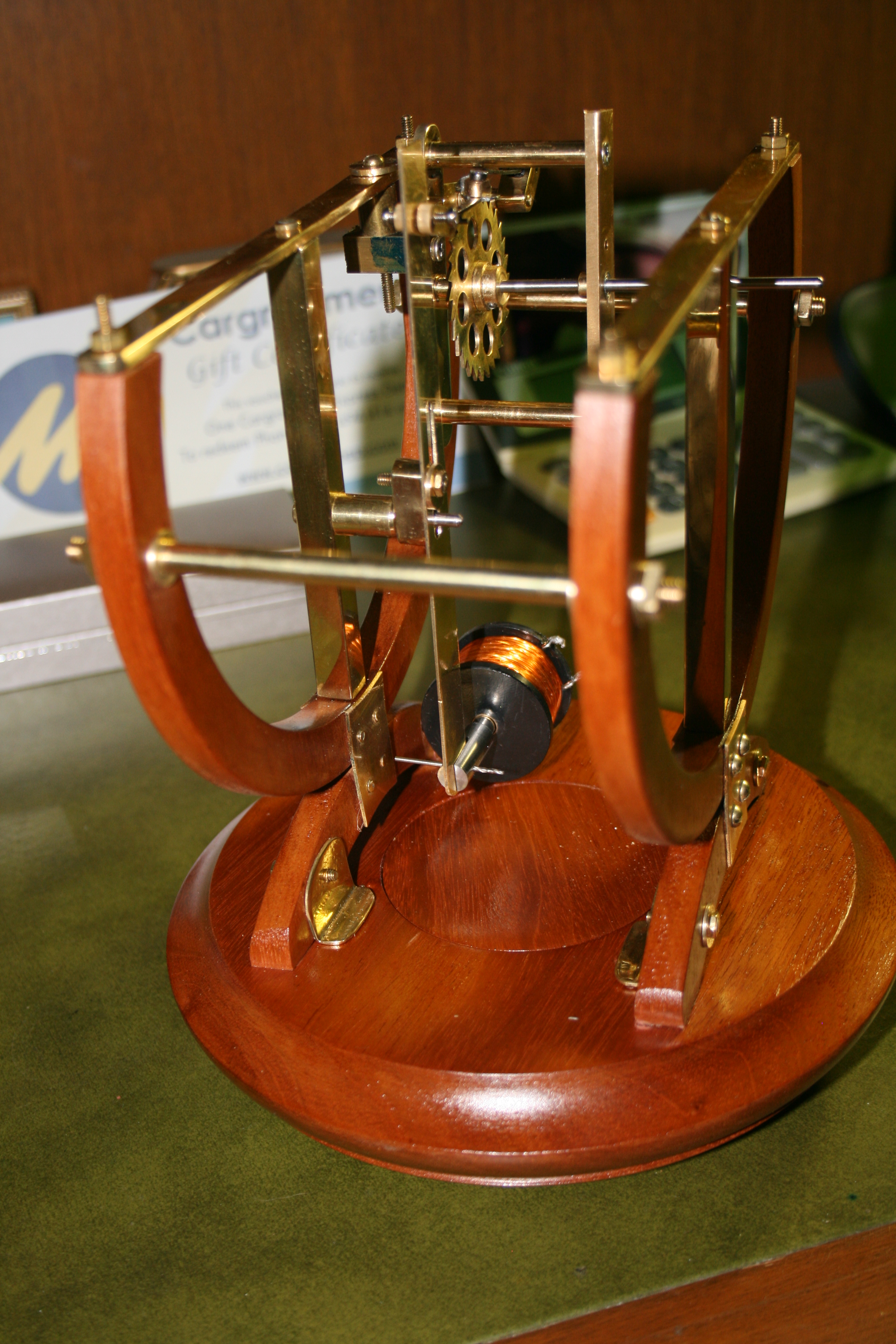
Another view makes the interaction between the armature and the coil a little clearer. |

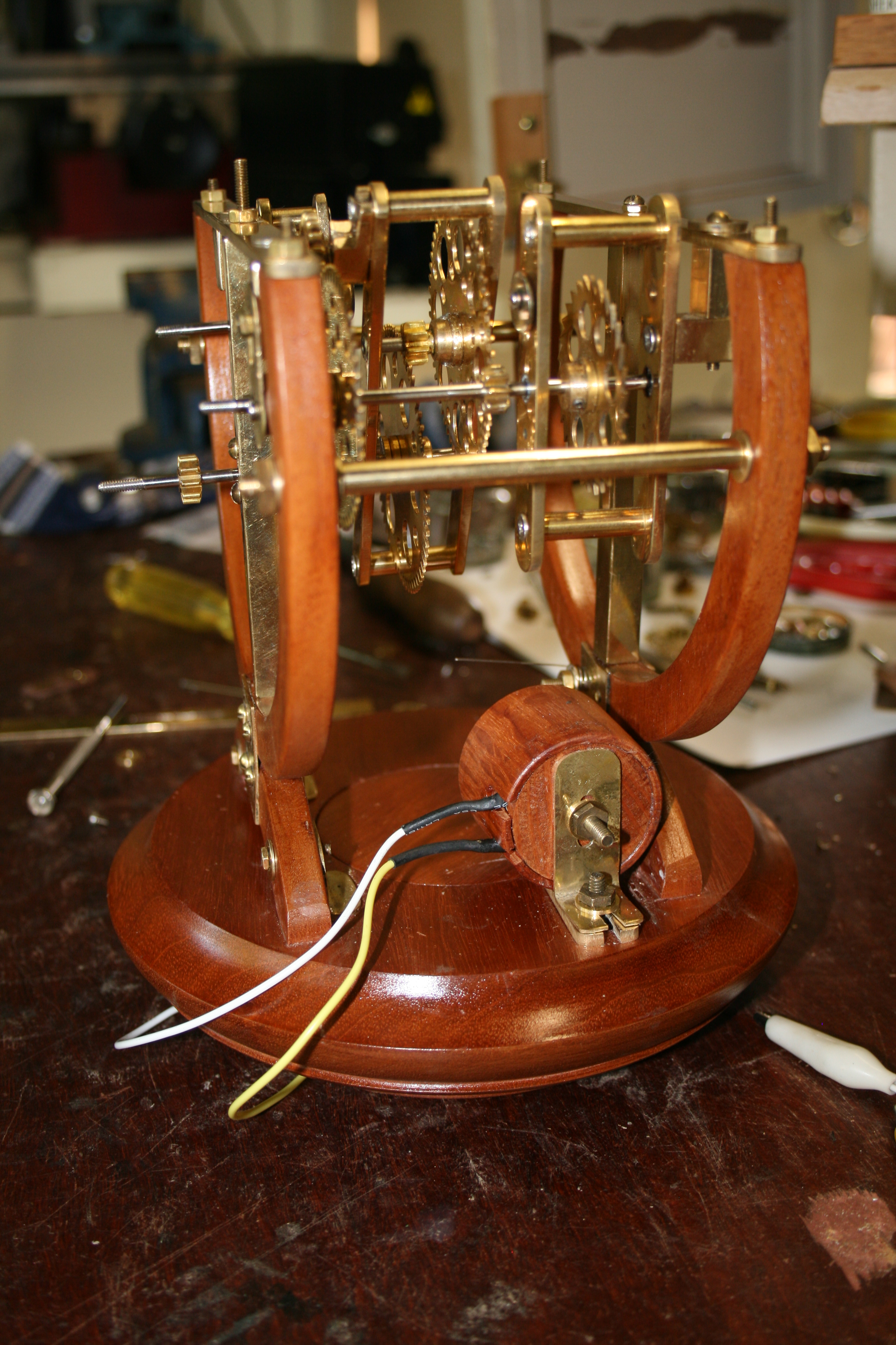
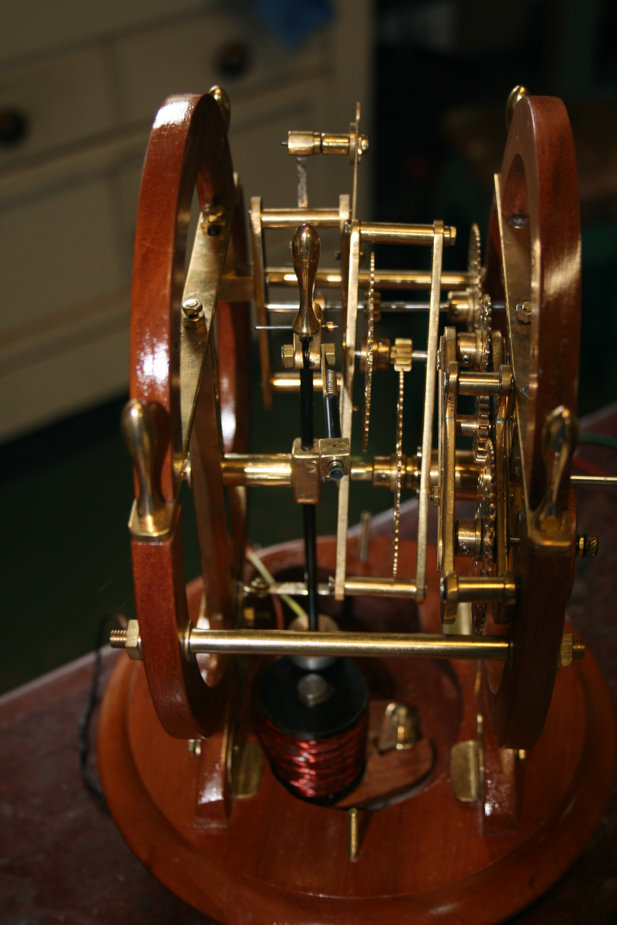
The clock is getting close to completion as this side elevation shows. |
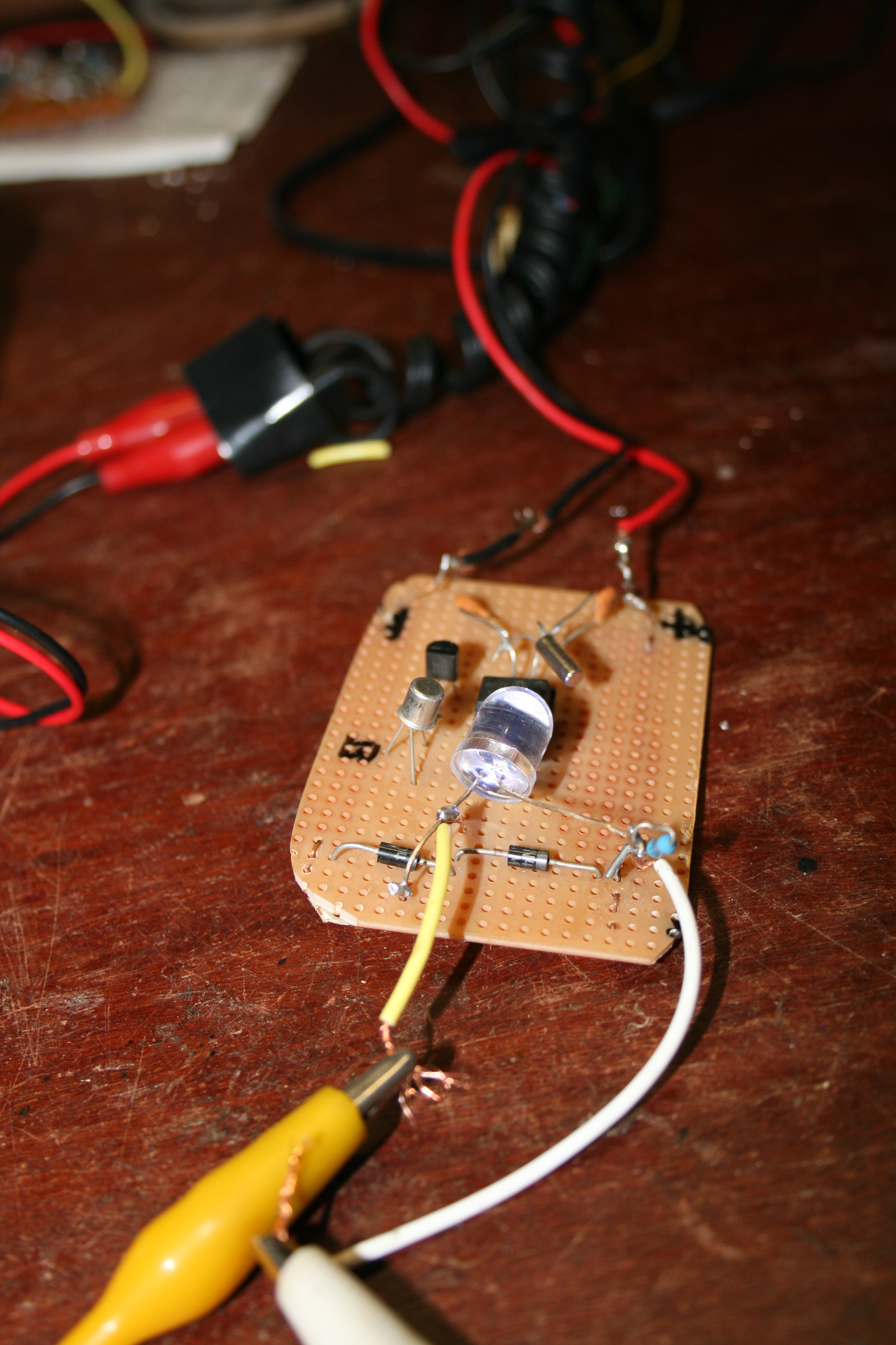
One version of the switch. This is what the switch that has been buried in the lidded box looks like. |
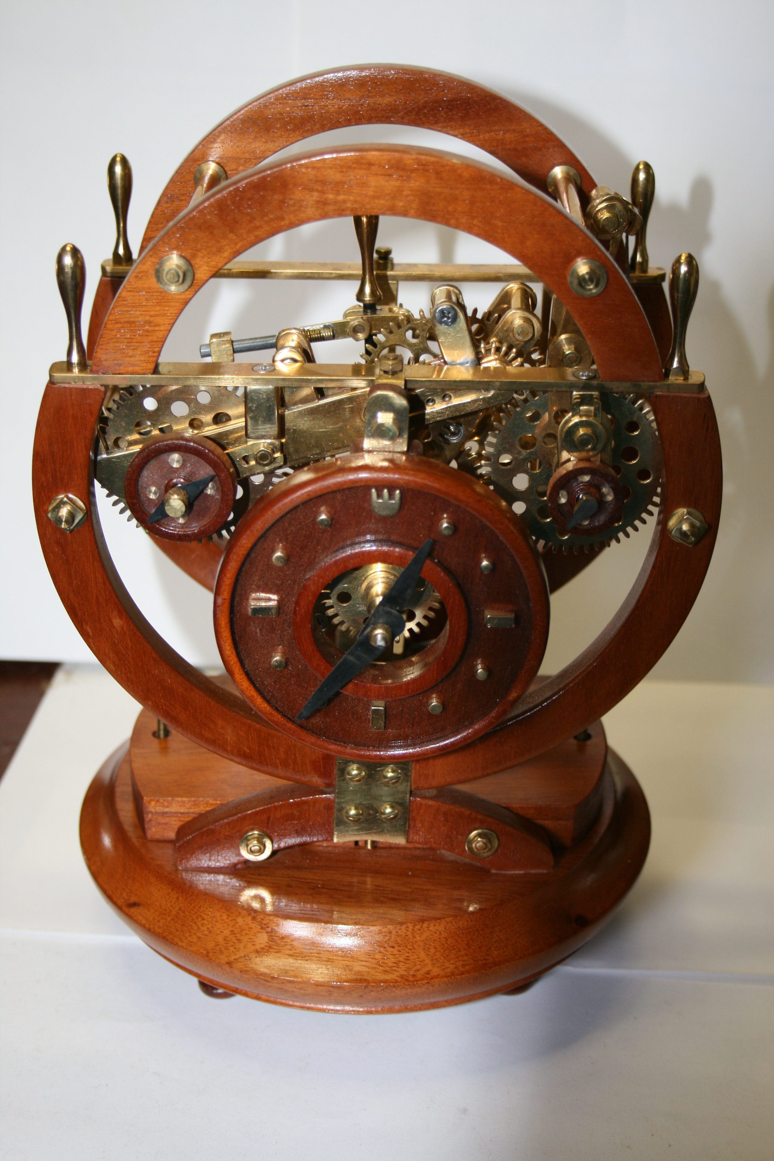
The clock is now almost complete and running well. My original idea of using a conventional lidded box lid had to be abandoned when it was obvious that I could not use an air solenoid mounted on its side. It was necessary to change the design (wood turners have turned on- the- job changes into an art form there are never any errors they are simple described as design changes ) and added an oblong boxed lid which I have covered with a polished brass plate. . |
