The Electronic Components of Clocks
| Stage 1
It was never my intention to get into electronics, nothing could have been further from my mind. The idea of just winding a coil was challenge enough to give me heartburn. But after my experience with the Brian Law clock I thought the advantages of electrical powered clocks, even though I didn’t have the faintest idea how to make them, seemed to me to be overwhelming. Up to the introduction of electrical technology into the world of horology, clocks were mostly driven by a spring or heavy weight. When the spring or weight is wound up, the clock movement is under constant tension. It is this tension that drives the clock through a gradual tension release mechanism called an escapement. Electric clocks that are driven by a magnetic coil are not under any tension at all. When the coil is energised it emits a magnetic field. This magnetic field can be used to attract an armature that is located at the bottom of a pendulum rod. As the pendulum rod is pulled forwards by the magnetic field, it can be used to push a wheel, known as a count wheel, which in turn drives the clock train. I think there are many advantages to this system but one of the less appreciated one is that it allows you to make pinions of softer metal. Most of the pinions in my clocks are made from brass rod. The pinions in more traditional clocks are made from hardened steel. My early ideas came from the Scotts Clock, the first commercial electric clock manufactured by the Eveready Battery Company in the US, which used a mechanical switch to turn the coil on and off. I made a number of mechanical switches with varying degrees of success. But it was always obvious that the combination of the limitations of mechanical switches themselves combined with my very limited skills at building them meant that I was always on the hunt for a better solution. At one stage I even managed to get a Hipp Toggle system working but it was clunky, temperamental and completely unreliable. On one occasion I was talking about the problem to a former radio tech I had met at a clock club I had joined. He said rather vaguely that what I needed was a slot switch. I had never heard of slot switches so I asked him for more information. It is not unkind to say that he was less than interested in helping and apart from providing a generic circuit with no details of any kind and which I did not understand anyway the conversation and contact ended. That was when my practice of education via the internet began. I discovered that slot switches were used in photovoltaic switches and so I sent emails to any company or organisation who I could find on the net that had any connections with photovoltaics to see if I could find a switch. They all drew blanks. I was feeling a bit disappointed when I received an email from the administrator of the Australian National University in Canberra. He was very encouraging and said he had passed my email onto the engineering section of the university and that somebody would contact me. I confess to thinking I would not hold my breath. Shortly after that I received an email from an engineer at the ANU named Bruce Condon. He asked me what I was trying to do and for the specifications of my coil and when I sent them to him he said he would build a switch. And he did! In due course this switch arrived in the mail (whenever I asked for a bill he ignored the email) with technical documentation but no instructions on how to use it. Eventually I figured out how to make use of it. Bruce went on to modify my switch to make it easier to use. When I talked to him about the voltage regulators I was building he sent me one he had made from the same kit I was using but his modification was much better than mine. I still use his modification in my voltage regulators. My repeated request for a bill so I could reimburse him were ignored. So I sent him a small clock I had made with a quartz movement and he asked me why I did that. I have lost touch with him now but I have a debt of gratitude to Bruce Condon and I will never forget the assistance he gave me and for which he refused to allow me to pay. In this grasping world in which we live his act of kindness to a complete stranger is simply remarkable. |
 My electronic clock journey begins. This was my first coil and pendulum experiment. As you can see Jess (the dog) looks bewildered by all the excitement. I tried to explain it to her but she just wants her dinner. My electronic clock journey begins. This was my first coil and pendulum experiment. As you can see Jess (the dog) looks bewildered by all the excitement. I tried to explain it to her but she just wants her dinner. |
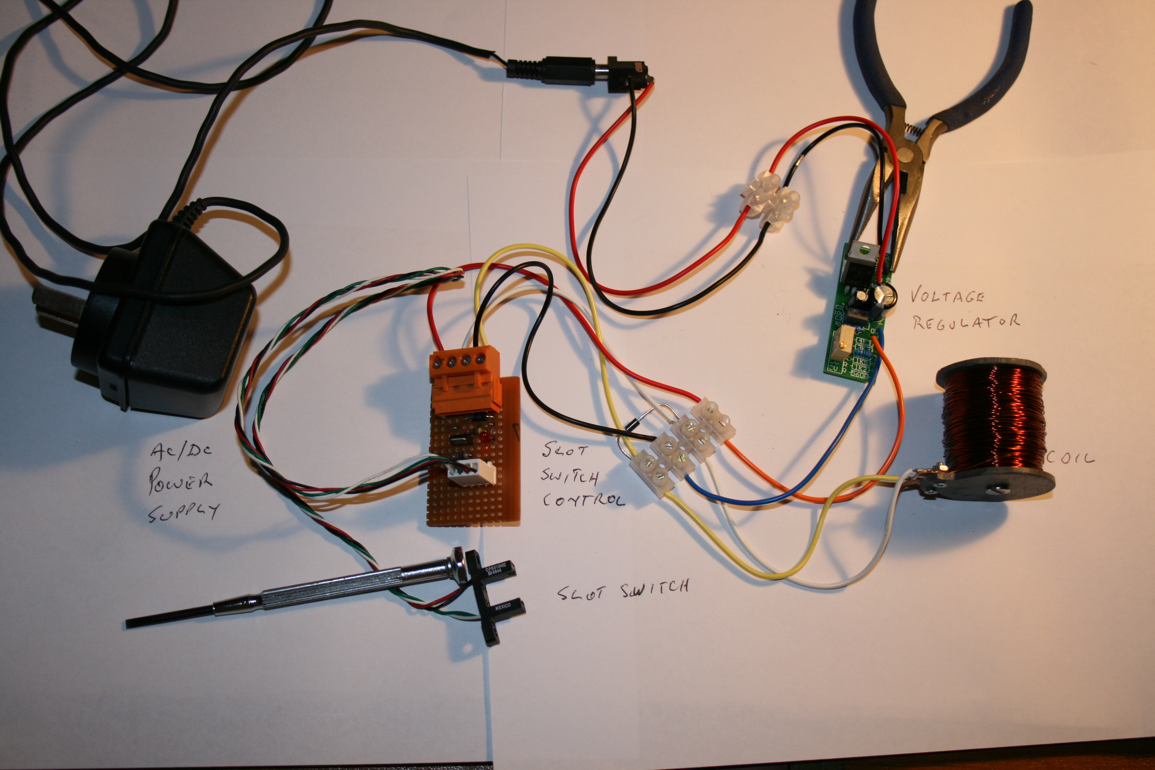 These are the electronic components for the slot switch controlled pendulum. It consists of a coil (about 10 ohms resistance) then a voltage regulator (Jaycar kit – modified) and the slot switch designed by Bruce Condon. These are the electronic components for the slot switch controlled pendulum. It consists of a coil (about 10 ohms resistance) then a voltage regulator (Jaycar kit – modified) and the slot switch designed by Bruce Condon. |
 Schematic of the slot switch. Schematic of the slot switch. |
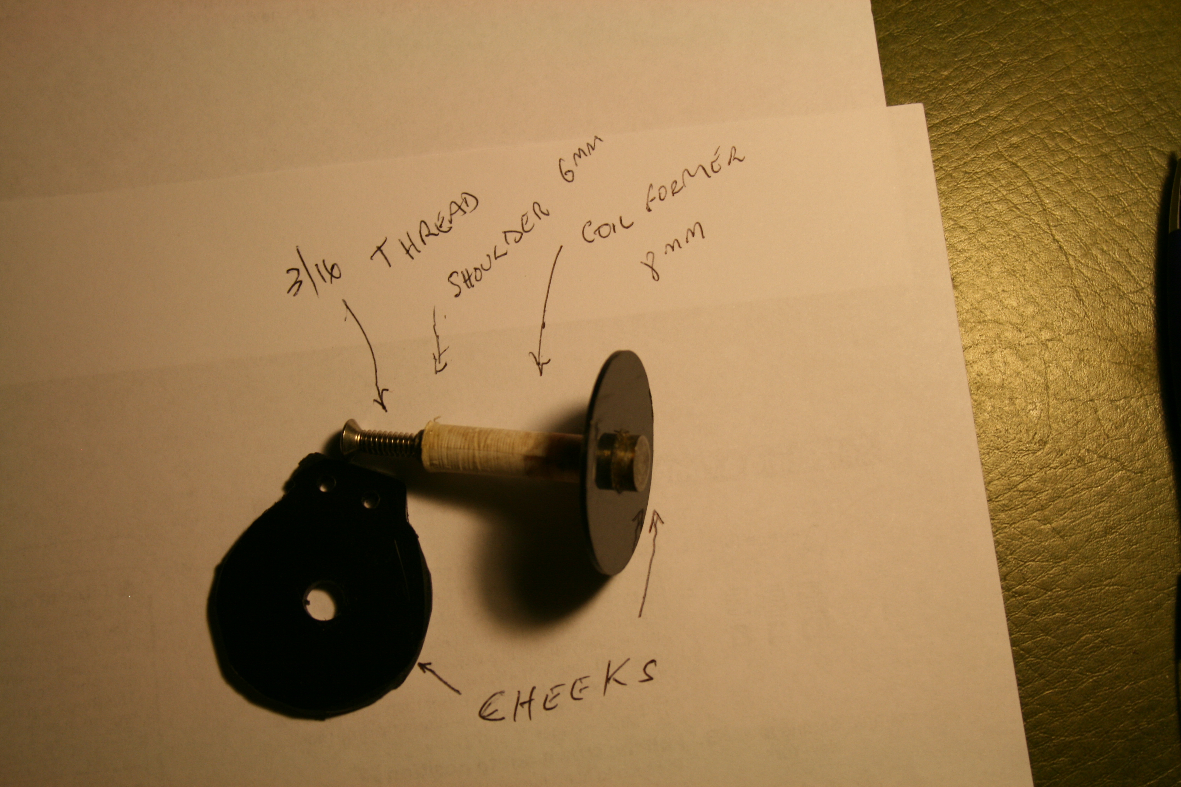
A solid coil former. Unfortunately I didn’t take photos of making coils however it is not rocket science. Make a couple of cheeks about 30mm round out of solid plastic (1/8″) and make a bobbin to the dimensions in the drawing. Get about a 1kg of .5mm copper wire and wind it one layer at a time between the cheeks as neatly and as tightly as you can. until the wire fills the space between the cheeks. I wound my first coil on my wood lathe with a home made hand-winder attached to the hand wheel on the headstock of the lathe. It took a while but eventually I had a coil that allowed me to begin my experiments. Once you have wound your first coil they get easier. |

In the middle of the picture, beneath the count wheel shaft there is a slot switch with a small black plastic flag .The brass screw attaches it to the pendulum rod. There is a 2mm slot in the black flag. The slot switch consists of two diodes one sending and one receiving. As long as the contact between the two diodes is blocked by the plastic flag, the circuit is closed. But when the slot in the flag lines up with the two diodes, current is allowed to flow thus switching the coil located beneath the armature at the bottom of the pendulum rod, on. This momentarily brings the coil to life and pulls the armature towards it which in turn pushes the lever on the count wheel and drives the clock to the next tooth. |
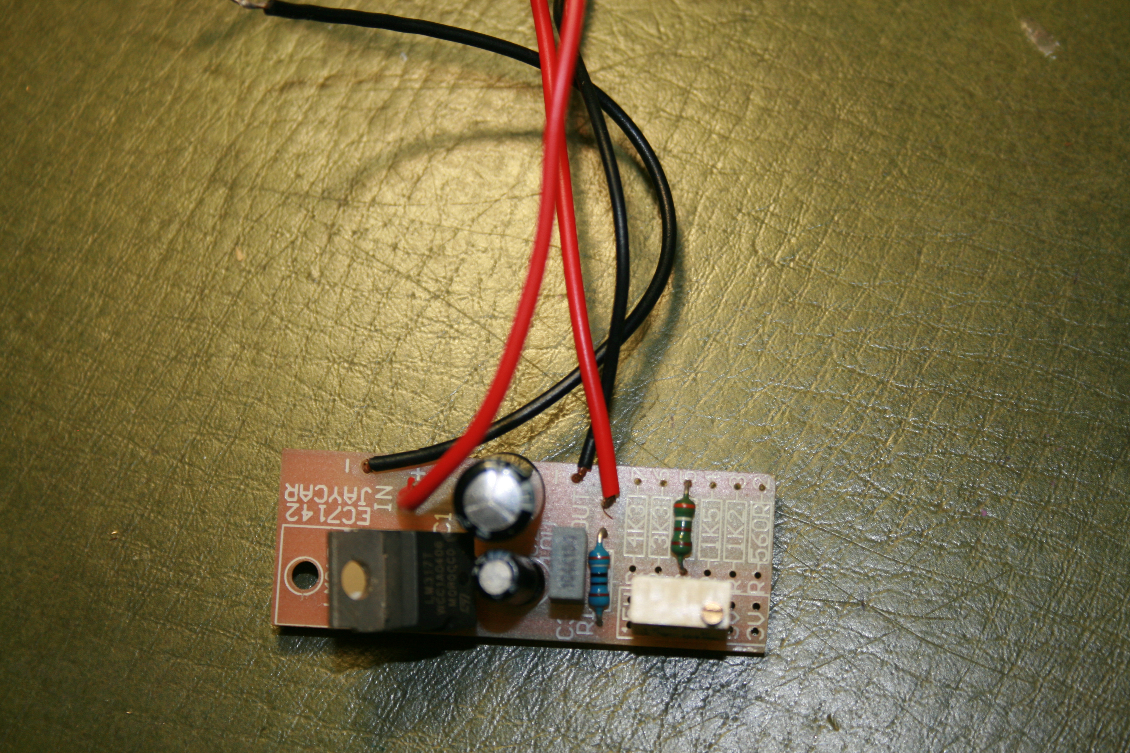
This is the voltage regulator I use in all my clocks. It is a Jaycar product that has been modified. The original circuit had a number of fixed resistors offering fixed voltages ranging from 3v to 15v but because I wanted variable voltages I removed them and replaced with a variable pot. Bruce Condon modified it further by providing this alternative variable pot with very fine adjustments. These adjustments are achieved by a small screw in the top and one complete turn of the screw equals about 1/10th of a volt. It is an excellent product. |
| Stage 2
After making a number of pendulum clocks I was looking for a better alternative. Basically what I wanted to do was to make smaller clocks and this was difficult as long as I was limited to the use of a pendulum. I am a member of a site on the net called ML Horology which is used by clock makers and would-be clock makers. One day one of the members of this site named Bruce Breimon who lives in California floated the idea of a different sort of switch/motor that used the same 32k crystal that is used in Quartz clocks. While I had little understanding of what he was talking about I was very interested. Bruce went on to develop the switch and also write the software to drive it and I reproduce it here with his permission because, like me, he is interested in helping anybody who has an interest in making clocks. Bruce’s original idea was to make a clock that was similar to the Lazy Clock that has already been published on the internet. This is a highly ingenious clock that uses a solenoid to move the hands forward once a minute. I am told that some Russian horologists used a similar idea earlier in the last century. I don’t think there is much new in horology. What I wanted to do was to move hands more quickly than that and fortunately the software that Bruce wrote provided variables that could be changed to allow me to do this. Both Bruce and I have made a few modifications to his original switch but the basics remain the same. I remain deeply grateful to Bruce for his innovative thinking and his willingness to share it with this Australian bloke he has never met. Such is the nature of those engaged in horological pursuits. Sharing what you do and how you do it is the raison d’etre in the clock making community. Without this free exchange of ideas and expertise I would not be doing what I am now doing. |
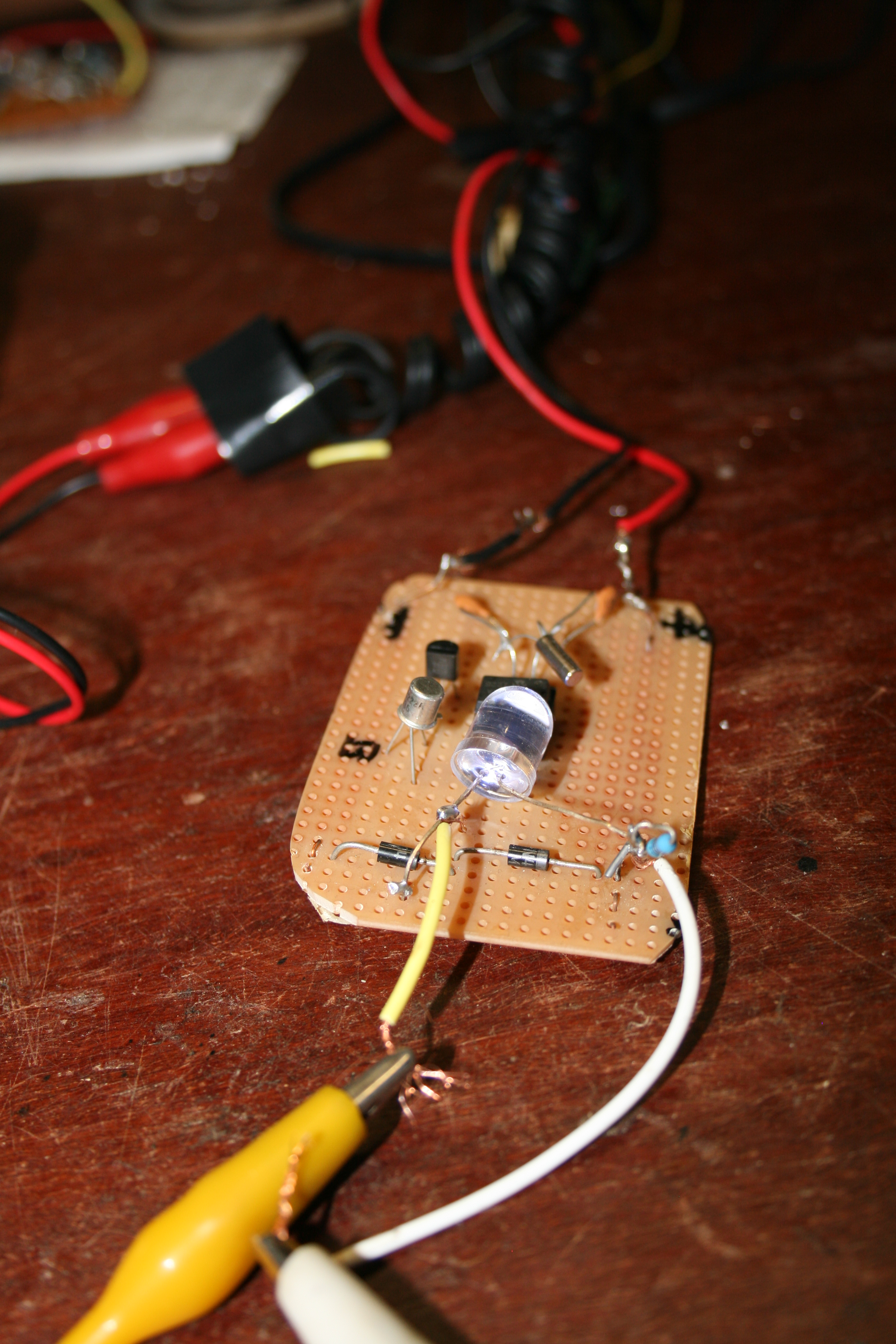
This is one of Bruce’s original switches. Behind the LED is an 8 legged integrated circuit. It is a 12f683 and I will talk a little more about it in the section on software. |

The original circuit. Produced with Bruce’s kind permission. This is the original circuit. There have been some minor changes including the replacement of the variable ceramic capacitor. Also I am now using a BC639 transistor and another voltage regulator to allow me to use higher voltages for the coil. |
Top of clock 4. This is a modified version of the switch. When I was modifying clock 4 which has large wooden wheels, it became obvious that I needed more voltage to the coil than the 5 volts the IC is limited to. So I used a second voltage regulatorwhich is variable up to 12 volts with the other set to 5 volts. I was to subsequently discover that there is a simpler way to do this. All that is required is to insert a 7805 regulator and a couple of capacitors into the circuit board which would be much less demanding of space and require less components. |
This provides a second perspective of the switch. |
An untried alternative. This is an alternative control mechanism for a pendulum clock which was sent to me by somebody who had read my article in The Australian Woodworker. I am yet to try it but the person who sent it to me assured me that it worked well. I will probably build it at some stage. |

his photo is out of order but gives a much clearer idea of now the slot switch and pendulum rod interact.
Upgraded Switch As mentioned earlier in this page the voltage required to drive the coil varies a bit from clock to clock. Ideally, a voltage to the coil of approximately 7 volts is on average about right. On the other hand the voltage to the IC is limited to 5 volts. Anymore than that will blow it up. So what I needed was a switch which outputs regulated voltages of 5 and 7 volts simultaneously. This is not difficult problem for those skilled in electronics but it was for me. Happily I have been able to upgrade the switch I build using a 7805 regulator control the voltage to the IC while allowing upwards of 7 volts to pass to the coil.
|
