| A brief comment on software. |
| I am not a software programmer and do not write code. Years ago I did a course to learn to program in basic and while I understand some of the fundamentals have never had any reason to try to take it any further. So, once again I am indebted to people who do particularly Bruce Breimon for writing the code we needed to get his switch to drive an air solenoid. He wrote it to include variable parameters to allow anybody using it play with numbers to vary the way the programme operates for any specific purposes. I will include a few examples of the variables in action as a small chart that should allow extrapolation to achieve a variety of outcomes. Additionally my oldest son Clinton who, as well as being a reference point for my electronic questions, has also written some software that will allow me to program my chips to control both air solenoids and also simple coils..
At the heart of each switch is an integrated circuit (IC) called a 12f683. This is the chip that I programme to control the frequency of the coil or air solenoid activation. As I said at the beginning of my webpage, this is not a “how to” document but rather an “if I can help you I will” document but I will include some detail where I can. If you have any other queries I will help if I can. In order to program chips (ICs) you need a programming system. When Bruce started he chose the PICkit2 programming system which I also chose because it is an effective tool. It does involve some expenditure and since the Aussie dollar has crashed relative to the US dollar, things have become a bit more expensive. If you have a look on EBay you will see some copies for sale. If possible I recommend you stick with the original US version because the programming board is superior to the copies. While the Chinese version of the programmer worked, the programming board that came with it did not. As well as the PICkit2 programmer you will also need a system to compile the programme you have written, copied or altered, before transferring them to the PICkit programmer. Bruce and I use Microcode Studio. |

I have reproduced Bruce’s switch circuit. This photo appears elsewhere but is reproduced for convenience. I have modified Bruce’s original switch for my own purposes. For example, while Bruce uses batteries for his clocks, I prefer AC/DC supplies because I want to drive heavier coils. So I have changed the 2n2222 transistor to a BC639 because while it operates the IC side of the circuit at 5v satisfactorily, I need more than that, in some cases in excess of 9 volts for the coil and the 2n2222 struggles with that sort of voltage. I also use a second voltage regulator not shown in the circuit. In addition I use a forcing resistor of about 100 ohms between the IC and the base of the transistor. |
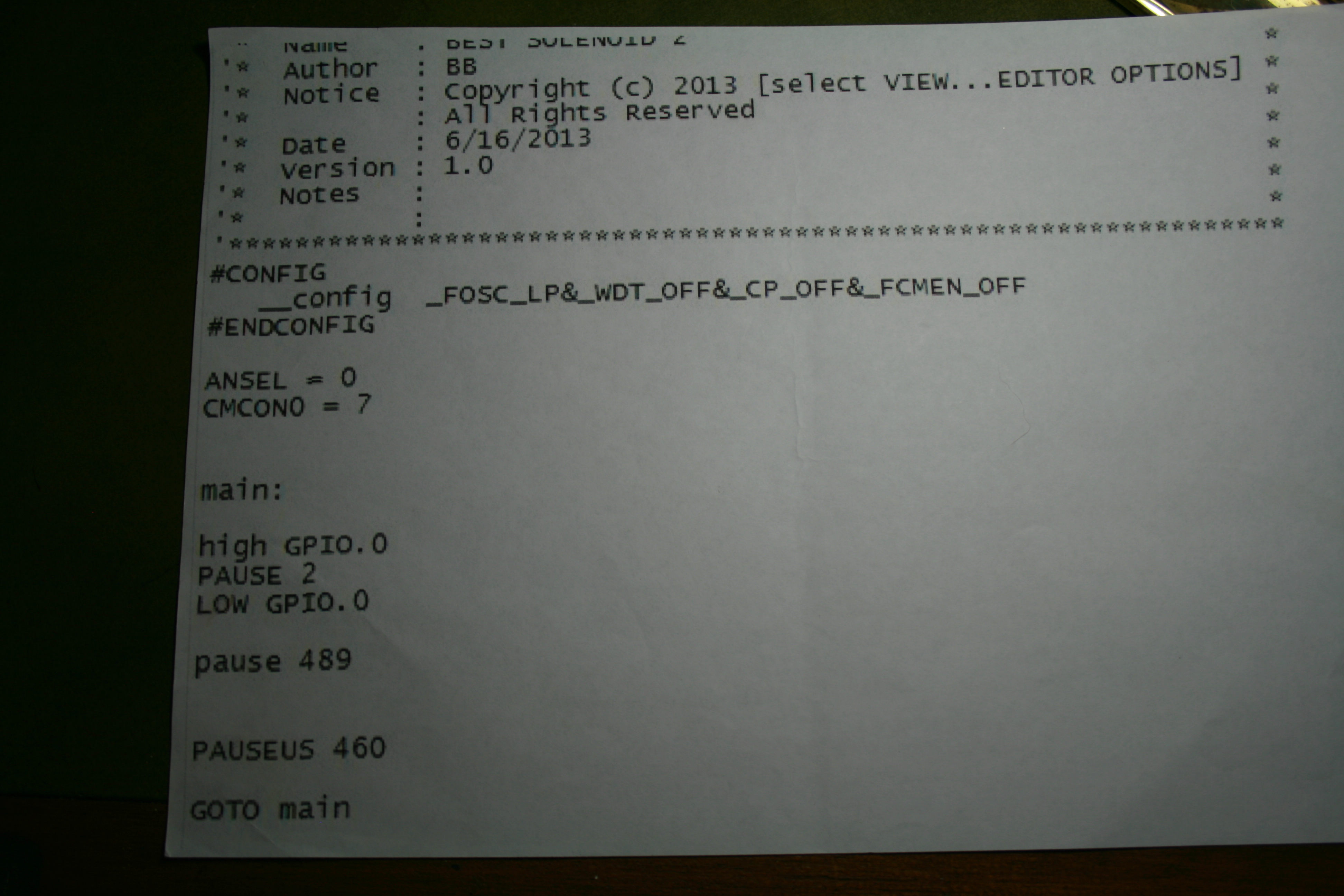
This software is re-produced with Bruce’s kind permission. His original objective was to have the solenoid activated once every 60 seconds which the numbers you can see against the pause and pauseus commands achieve. If you modify those to, for example, Pause 12 Pauseus 1000, you get about 37 activations per minute. As you fiddle with these numbers you can get pretty close to the activations required to make the clock quite accurate. |
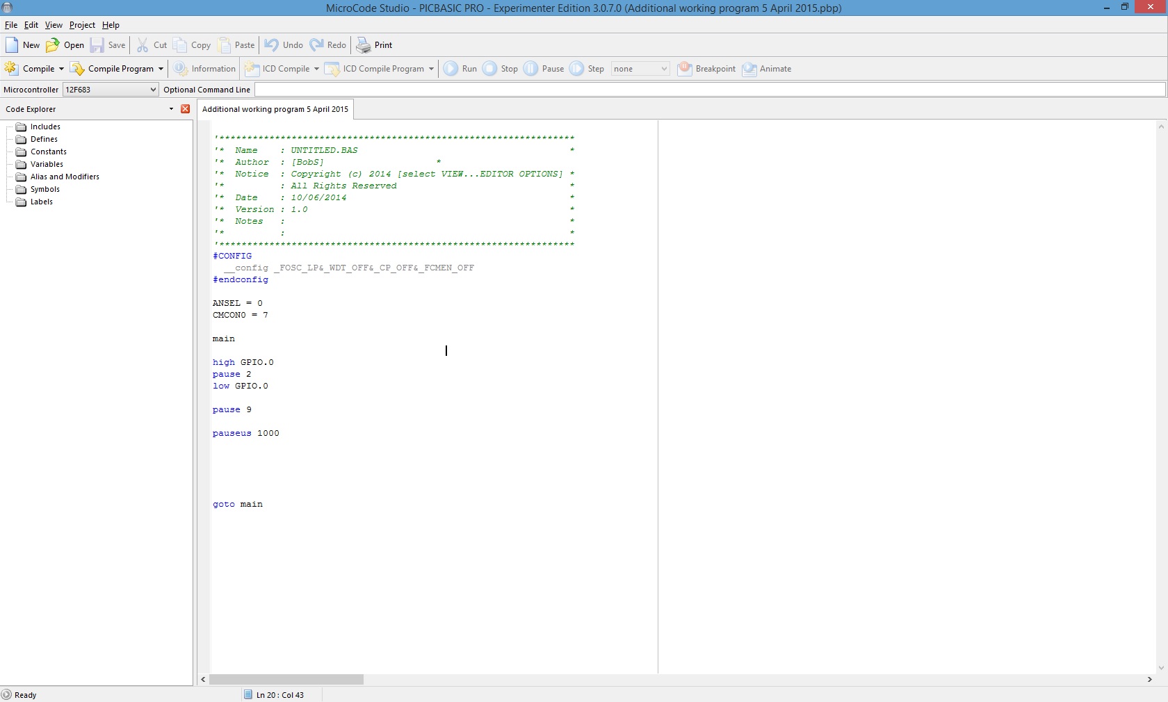
This is a screen shot of Micro Code Studio. I will provide a step by step process for the chip programming process. After you have completed the program you plan to use, select File and then save it. When the saving is completed select Compile which is the box immediately below the word New. When you do that a box will flash onto the screen and shortly after it will tell you that it has been successfully compiled. If this does not happen there is an error in your code which you need to find and rectify. When this is done go through the same steps again. |
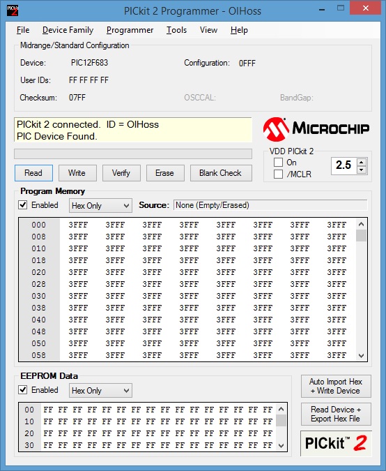 This is a screen shot of the PICkit2 presentation. The device being programmed in this case is a 12f683 chip which appears next to the word Device on the top left of the page. This means that it is ready to accept a program. Select File (to left hand corner) which will invite you to import the HEX file. To do this go back to the Micro Code studio page (they should both be active on your computer screen) and select File. This should take you to your recently saved file. Highlight it by selecting it at then select Open. Your PICkit2 program page will then tell you your HEX file has been successfully imported. Then select Write and the window in the PICkit2 will go through a series of programming steps automatically. It takes a few moments. You will then be told that the programming was successful at which point you can removed the IC from the programming board and insert it into your switch. This is a screen shot of the PICkit2 presentation. The device being programmed in this case is a 12f683 chip which appears next to the word Device on the top left of the page. This means that it is ready to accept a program. Select File (to left hand corner) which will invite you to import the HEX file. To do this go back to the Micro Code studio page (they should both be active on your computer screen) and select File. This should take you to your recently saved file. Highlight it by selecting it at then select Open. Your PICkit2 program page will then tell you your HEX file has been successfully imported. Then select Write and the window in the PICkit2 will go through a series of programming steps automatically. It takes a few moments. You will then be told that the programming was successful at which point you can removed the IC from the programming board and insert it into your switch. |
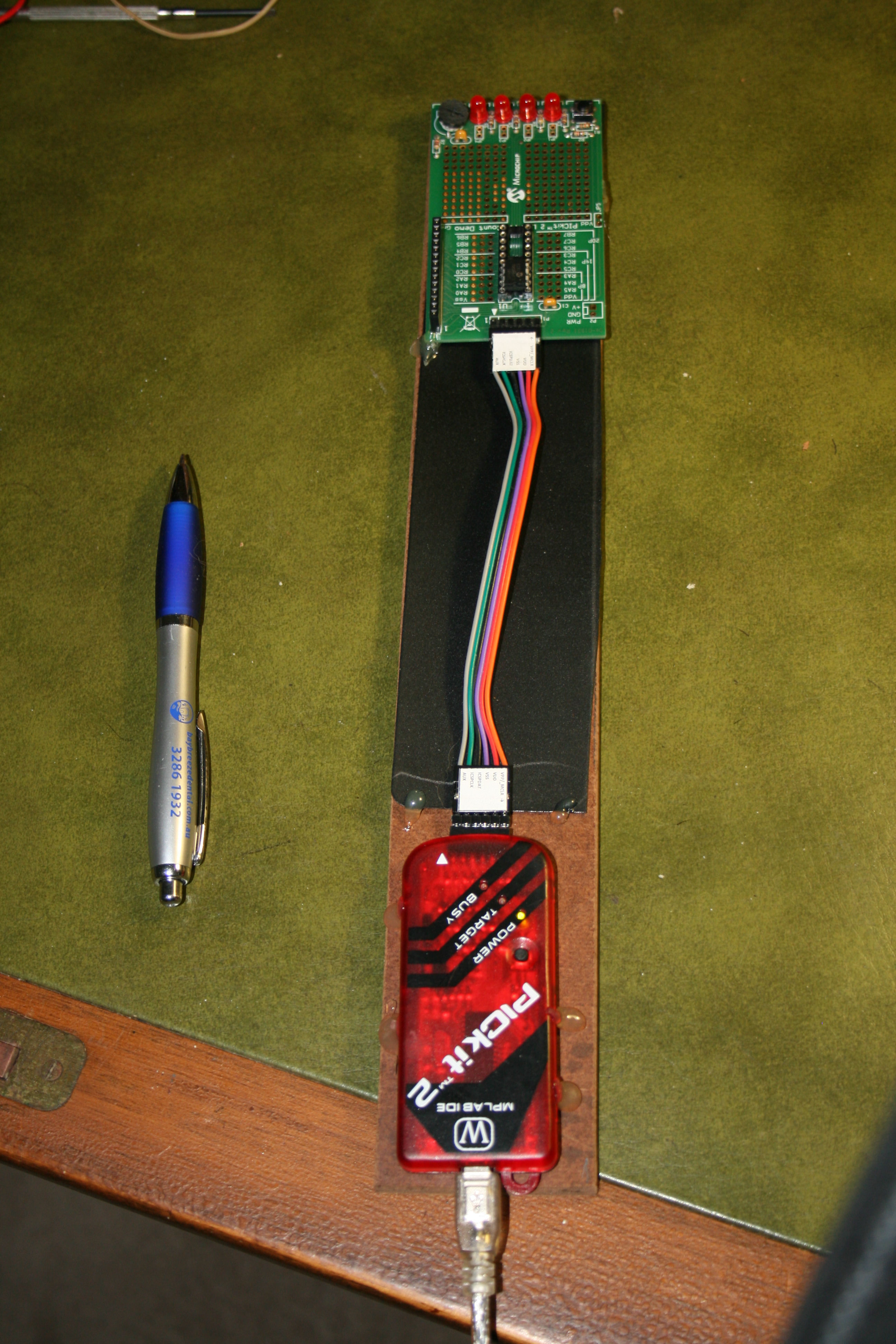
The PICkit 2 programmer connected to the programming board. This is the Chinese version of the PICkit2 programmer purchased on EBay. It is cheaper than the Microsoft original however the programming board that came with it did not work. The programming board featured in the photo (the green device at the top of the picture) is a Microchip original. Clinton actually uses a breadboard to program his chips with a circuit he set up himself. The first Microchip programmer I purchased developed a fault and nobody at Microchip seemed to interested in my problem. The Chinese version of the programmer is about half the cost of the Microchip version. Purchasing this equipment was easy, getting it to work was more difficult. The cord you can see in the picture plugs into a USB port on your computer. |
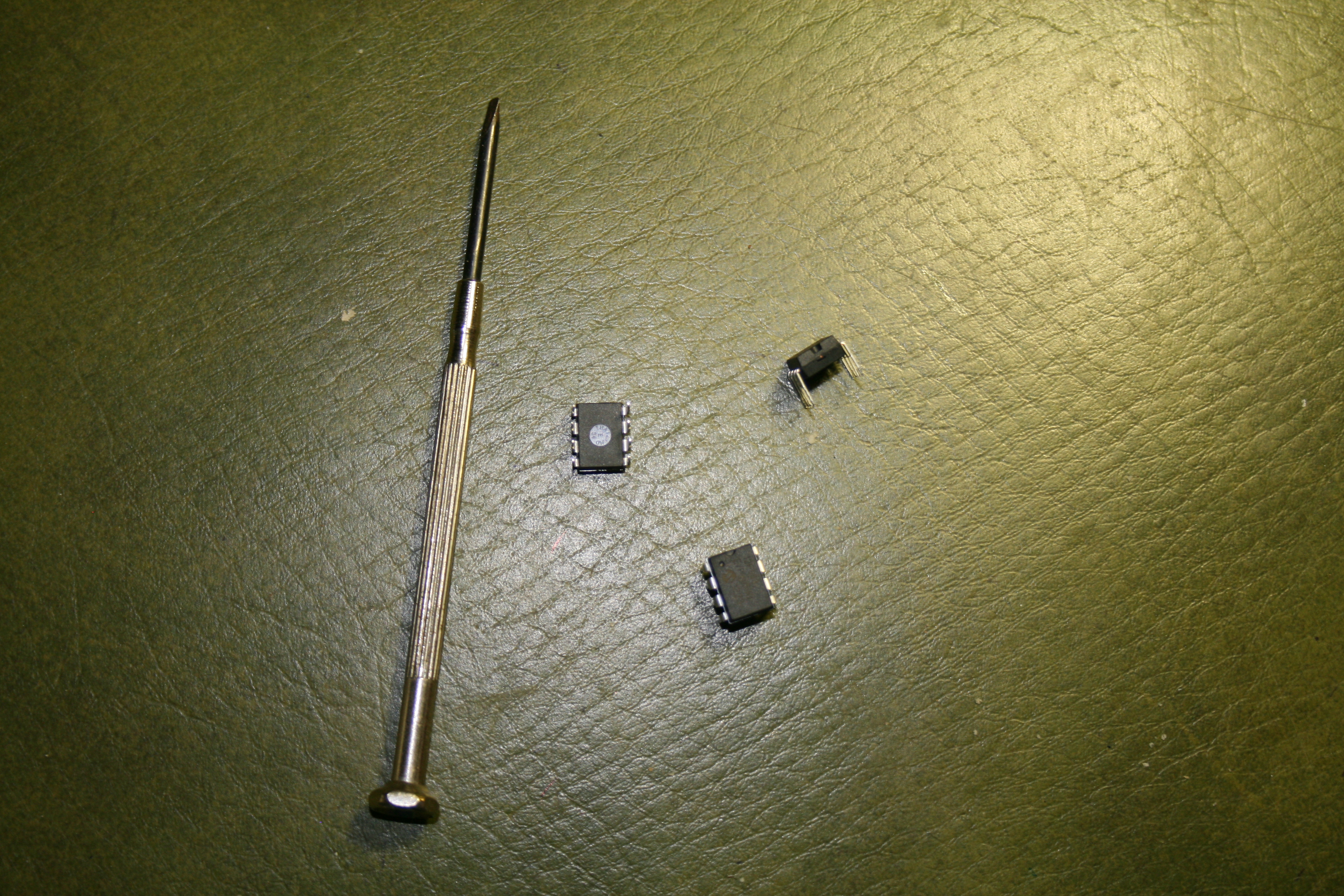
This is what the 12f683 looks like. They have 8 pins and are fiddly to use. Be prepared to be patient. |
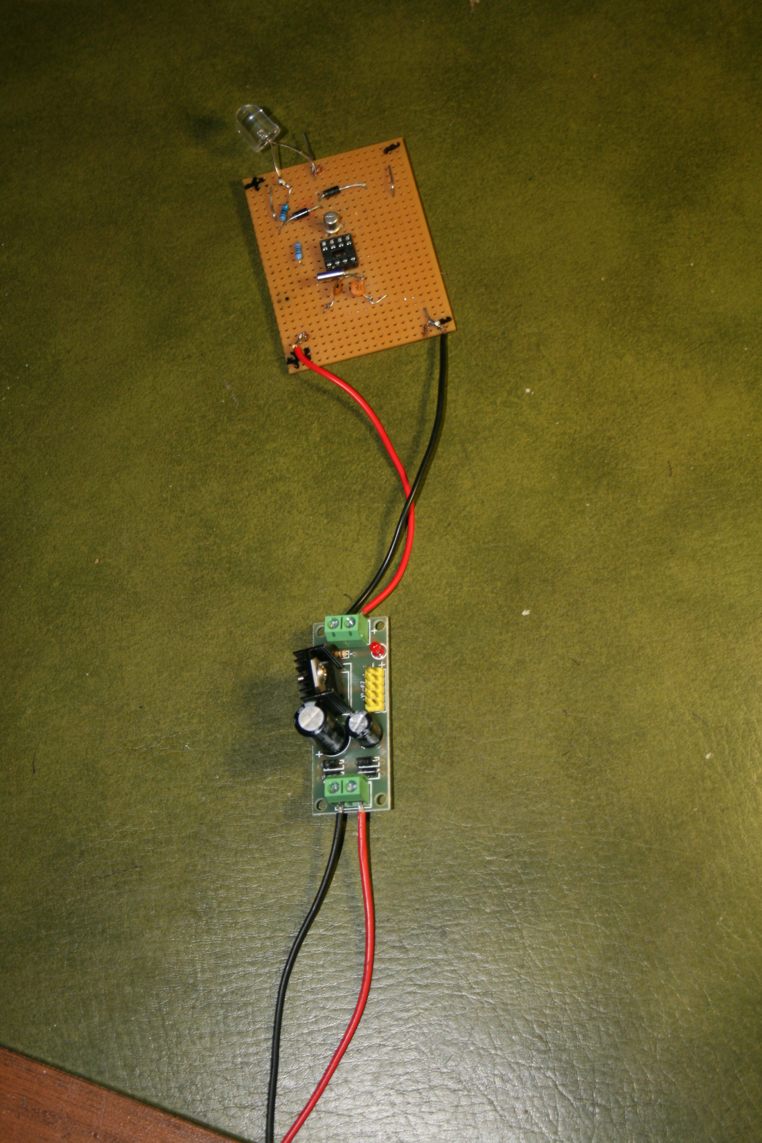
The test bed. This is a switch connected to a 5 volt voltage regulator. I use this to test that the programming was successful by counting the number of times the LED flashes. |
What follows is a series of instructions that should get your chip programmed. Because all but three of my clocks have different pendulum lengths, the setting of the pulse rate has been a matter of trial and error.
Your are now, as they say, ready to cook with gas. Good Luck. |
| Included below is a small chart which should give you some idea of the outcome when you make changes to the Pause and Pauseus commands in the program.
Pause 10 Pauseus 3000 33-34 pulses per minute Pause 10 Pauseus 2000 35-36 pulses per minute Pause 9 Pauseus 500 43 pulses per minute Pause 9 Pauseus 1000 41 pulses per minute. These figure should give you enough information to extrapolate the figure and fiddle to get the sort of outcome you are after. July 2016 My experience with the PIC Basic Pro program has been mixed. Suffice to say that I have not been able to get the numbers fine enough to provide the accuracy I would like to achieve. I have clocks that may be losing slightly with a, for example, Pauseus of of 341 but then gains a bit if I change it to Pauseus 340 (reducing the Pauseus number speeds up the clock) which can be a bit frustrating. Clinton, my oldest son, has written a program in Machine language with an additional parameter so that there are three options instead of two. I will be using this program in this clock but it will take a while before I know what the outcome has been. |
