 I made this clock some years ago. The original version had eight pillars and a glass door. It also had a novel dial that I thought was a good idea at the time. Initially I thought it was ok but grew to dislike it, not only because it didn’t work all that well but also because my workmanship was poor. I made this clock some years ago. The original version had eight pillars and a glass door. It also had a novel dial that I thought was a good idea at the time. Initially I thought it was ok but grew to dislike it, not only because it didn’t work all that well but also because my workmanship was poor.
So I decided to modify it in a number of ways. I liked the top and the base, so I replaced the eight pillars with four pillars and used cedar veneer to cover the surplus holes. As a matter of interest the four pillars I have used are testimony to the fact that a wood turner can find use for just about any timber. They are turned from Sheoak which is normally an almost pink to red colour. However the tree that I took this timber from had been through a forest fire and heating the sap seems to do strange things and the colour changed to a beautiful chocolate. I have made a number of things with this timber and unless you are familiar with what happens when it gets cooked you would tend to think that it was beef wood or similar. For some time I have been looking for an alternative to the slot switch controlled pendulum clocks I have been building. Clocks 9 and 10 were an initial step in that directions with the system in clock 10 being my most favoured. So I decided to see if I could up-scale the mechanism in clock 10 to drive this wooden wheeled clock which is much larger and requires more power than the smaller brass wheeled clocks.ork by the scientifically proven method of trial and error. Many trials, many more errors. Having successfully completed the refurbished case, I turned my attention to the mechanism. I replaced the wooden count wheel with a brass count wheel about a third of the size. While clock 10 operates quite happily at 5 volts the 2n2222 transistor I have been using was not capable of creating enough energy to drive the larger movement. I tried increasing the voltage to 7 volts but all this achieved was to burn out the IC which is pretty unhappy with anything over 5 volts. My problem was that input to the IC was limited to 5 volts but the coil needed, or I thought it needed, in excess of 7 volts. So I decided to install a second voltage regulator into the circuit. This voltage regulator which could actually deliver more than 12 volts would go to the coil and the second voltage regulator set to 5 volts would power the IC. This was successful. However, when I tried to increase the voltage to the coil to 7.5 volts the 2n2222 transistor began to heat up and eventually burnt out. So I replaced it with BC639 transistor that was capable of 1 watt and 1 amp. Initial indication were positive but the clock would still stop. Even increasing the voltage to over 10 volts did not guarantee sufficient energy to drive the larger wheels. I then decided to try a BD139 which is a power transistor used in audio amplifiers. AT 8 watts and 1.5 amps I figured I could drive a truck with it and the clock mechanism is now going at voltage of 7.5v. But as we all know, the problem with clocks is that it take a long time to know whether they will actually work or not. So I will just let it run for a while, |
|
|
 The eight pillars and glass have been removed and replaced with four pillars turned from Sheoak that has been through a bush fire which changes the colour. The eight holes that the original posts had been glued in have been covered with red cedar veneer. The wooden count wheel has been replaced by a brass count wheel 1/3rd the size.
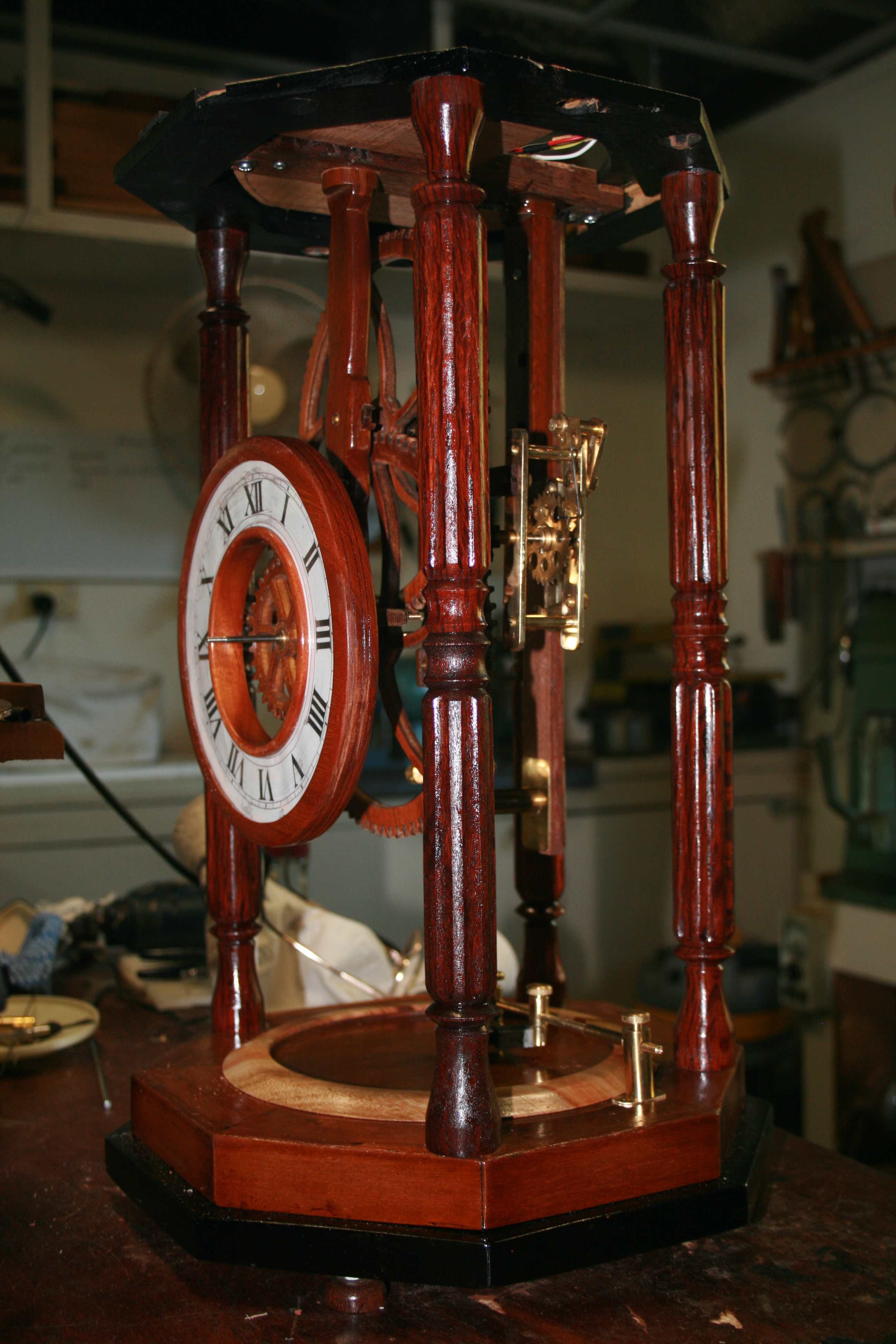
The new brass countwheel can be seen to the left and the brass rail at the bottom has two brass posts to restrict the travel of the shaft which drives the count wheel. The idea of the shaft is quite simple. At the top is a balancing weight. At the bottom there is an oblong armature made from steel that has been annealed to soften it. When the coil is turned on by the integrated circuit, the armature is attracted to it. This pushes a small arm that rests on the count wheel and drives it forward by one tooth. As soon as the switch turns off, the magnetism in the coil collapses and the drive shaft is returned to its rest position by counter weight. This has been installed at the top of the shaft. The shaft itself is made of carbon fibre which is the most stable material I could find to do the job. Invar, a metal used by old time clock makers is the most suitable but it would be cheaper to buy a piece of gold! |
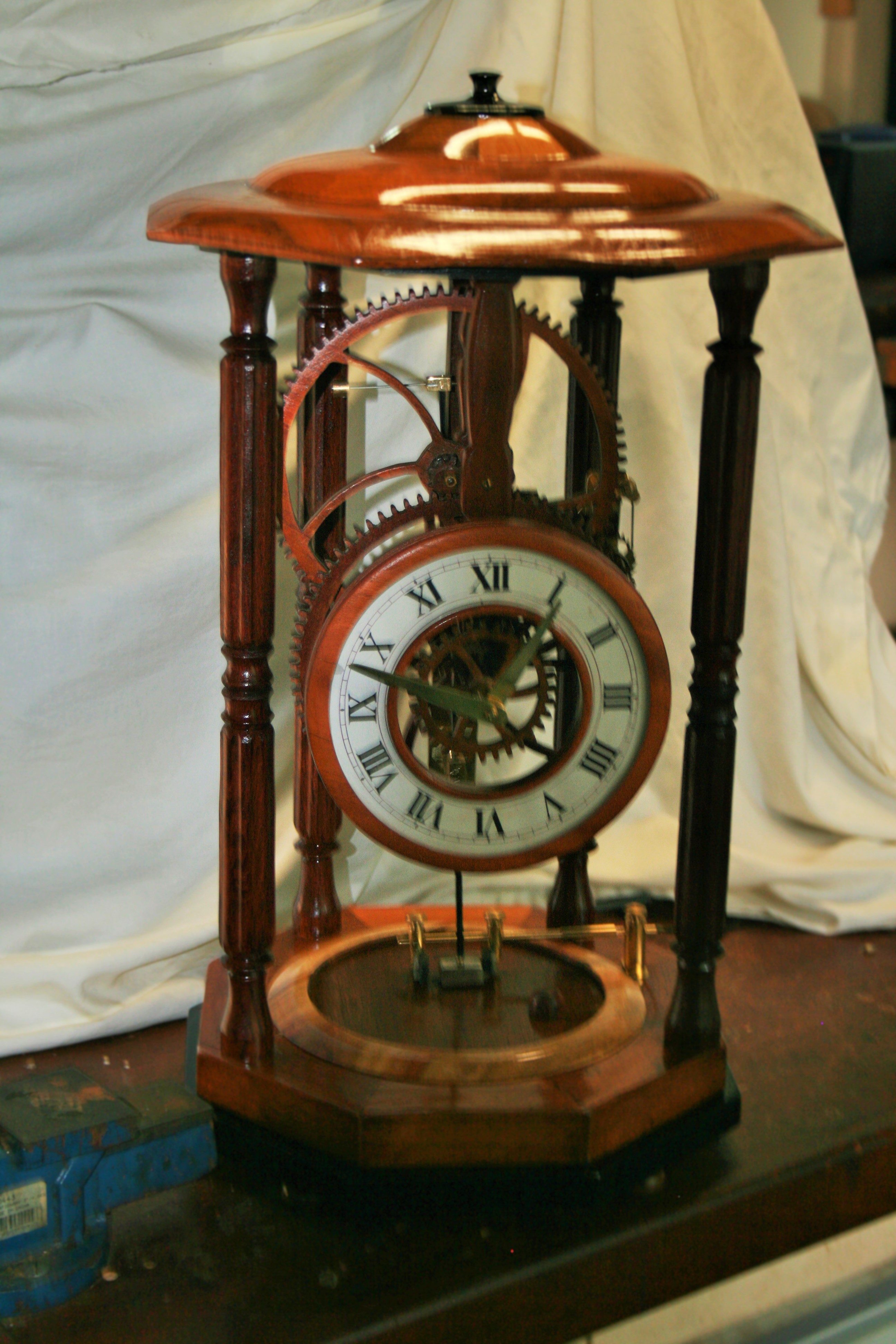
The modification is now complete. The electronics are covered in the electronics section. |
